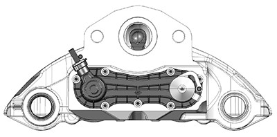
Fitting instructions are common to LA225, LB195, LB225, LC225, LNR225 & LV225 brakes.
 |
 |
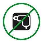
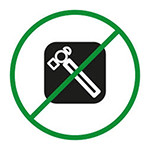
Do not use air wrenches or hammers. Their use will damage the product, prevent correct function and will void the warranty.
 |
 |
Text in green is offered as advice.
If you have any questions about the fitting instructions, or require further advice, please email technical@meibrakes.com
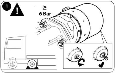
1. Ensure the vehicle is securely chocked before releasing the parking brake. Remove the wheel in line with the manufacturer's recommendations. Cage the spring brake or use a minimum hold pressure of 90 psi (6 bar). Remove the air chamber and disconnect the pad wear sensor cable (if fitted) from the caliper.

2. Make note of the pad wear warning indicator (PWWI) cable arrangement (if fitted) and remove the pads and retainer. Remove the pad retainer by removing the clip, washer and pin. Replace used parts with the new ones provided. Remove both pads and springs and visually inspect - replace if worn or damaged. Remove the guide sleeve protective caps, guide sleeves and bolts. Replace used parts with the new ones provided. Remove the old caliper assembly - use suitable lifting equipment for the caliper. Visually inspect and, if necessary, clean the carrier and disc - replace if worn or damaged.
Before removing the guide sleeve bolts ensure that the caliper cannot move or fall causing injury.

3. Remove the new caliper and guide sleeve kit from the packaging - use suitable lifting equipment for the caliper. Check that the new parts correspond with those that have been removed.

4.Grease both guide sleeves using the grease sachets provided. Slide the guide sleeves in to the bushes in the directions indicated above;
4a - short guide sleeve rubber bush without second boot on caliper (Type B)
4b - short guide sleeve plain bush with second boot on caliper (Type C)
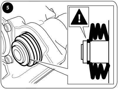
5. Locate the boot(s) into the sealing groove in the guide sleeve(s) ensuring it seals correctly all around the sleeve.
A little grease will help the boot slip into the groove.

6. Locate the plastic washer over the boot(s) to retain it in the sealing groove in the guide sleeve(s) ensuring the washer is in the correct
orientation.
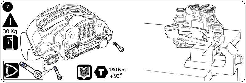
7. Ensure the carrier threads are clean and dry (free of lubrication and residuals of pre-applied adhesive). Lift the caliper over the carrier and locate the bolts into the carrier - use suitable lifting equipment for the caliper. Ensure the correct new bolts are used for each guide sleeve - the long guide sleeve has a pre-applied adhesive. If the caliper is being fitted away from the vehicle ensure the carrier is securely located to resist the bolt torque, at a location close to the bolt being tightened. Tighten both bolts to 180 Nm, then tighten by a further 900 - check that the caliper slides easily on the guide sleeves.
The pre-assembled pad retainer can be used to lift the caliper if done with care.
Never hold the caliper with your fingers between the caliper and the carrier - there is a risk of injury.
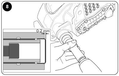
8. Locate the protective cap for the long guide sleeve into the caliper bore - protective cap and bore must be clean and free from lubrication. Press the protective cap into the bore ensuring it is seated squarely until the cap protrudes 0 to 2 mm from the cast boss.
Fitting the protective cap(s) can only be done after the caliper has been fully bolted to the carrier.
The guide sleeve boot(s) must be in a compressed condition or the caliper’s freedom of movement will be limited.
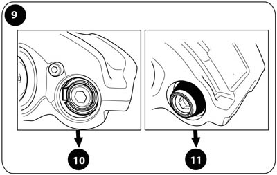
9. Identify the short guide sleeve bush type;
Type B - short guide sleeve rubber bush - go to 11
Type C - short guide sleeve plain bush - go to 10
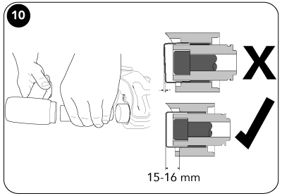
10. Locate the protective cap for the short guide sleeve (where applicable) into the caliper bore - protective cap and bore must be clean and free from lubrication. Press the protective cap into the bore ensuring it is seated squarely until the cap protrudes 15 to 16mm from the cast boss.

11. Slide caliper inboard and insert inner brake pad and spring.
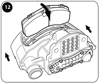
12. Slide caliper outboard and insert outer brake pad and spring.

13. Turn the adjuster clockwise until the pads come into contact with the disc - do not exceed 25 Nm torque.

14. Turn back the adjuster 3 clicks and check the pad-to-disc running clearance.

15. Check for free rotation of the disc. Refit the adjuster cap.
Opening or dismantling of the caliper is not authorised.

16. Locate the new pad retainer in the slot in the caliper and depress to enable the insertion of the pad retainer pin. Locate the washer over the pad retainer pin.

17. Press the clip through the pad retainer pin to secure.
It is recommended that the pad retainer pin, where possible, is installed with pin head uppermost.
 |
 |
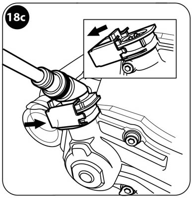 |
18. If the carrier was removed from the vehicle refit the caliper and carrier assembly in line with the vehicle manufacturer’s recommendations. Reconnect the pad wear sensor cable connector (where applicable).
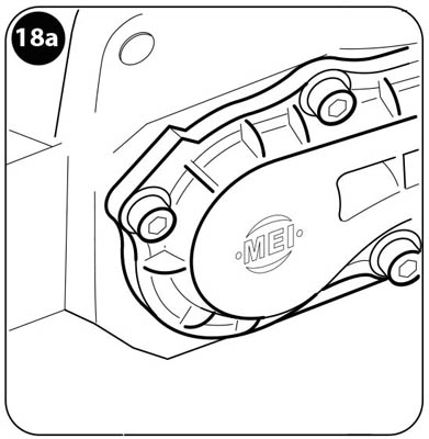
18a Chain cover without pad wear sensor - no action necessary.
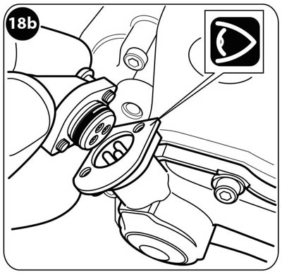
18b Chain cover with screw type connector - engage the connector and then tighten the 2 screws.
18c Chain cover with clip type connector - engage the connector and then push the clip firmly into place.
Ensure the pad wear sensor cable connector is clean and free from grease, dirt and moisture.

19. Refit the pad wear warning indicator (PWWI) cable and clips in the same orientation as when removed.

20. Remove the adhesive tape in the area of the air chamber attachment. Take care that no dirt enters the brake caliper.
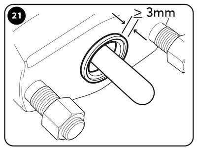
21. Visually inspect and if necessary clean the air chamber mounting and sealing surface - replace if damaged.
If the air chamber seal protrudes less than 3 mm the brake chamber must be replaced.
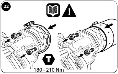
22. Refit the air chamber in the same orientation as when removed, in line with the vehicle manufacturer’s recommendations. Tighten the nuts to 180-210 Nm (unless specified differently in the vehicle manufacturer’s
recommendations).
In order not to tilt the air chamber during its attachment, the nuts must be gradually tightened symmetrically with a suitable tool.
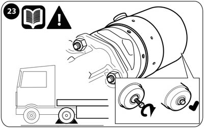
23. Replace the wheel in line with the vehicle manufacturer’s recommendations. Uncage the spring brake and apply the parking brake prior to removing the chocks from the vehicle. After releasing the parking brake, apply the brake 10 times then road test the vehicle.