Replacement of the sensor cover assembly should only be undertaken to replace a damaged sensor cover or wear sensor if there are any signs of water ingress then the complete caliper should be replaced.
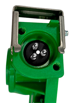
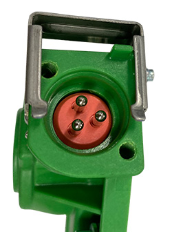
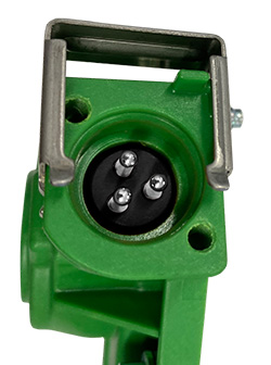
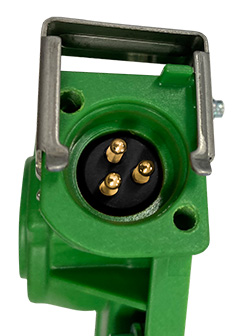
! Identify the type of sensor by the electrical connectors only replace with the same type. MEI ‘universal’ sensor covers can accommodate either screw type or clip type connectors.
 |
 |
 |
 |
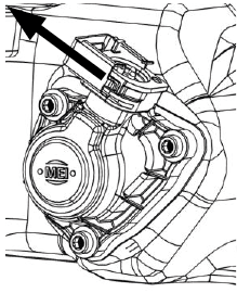 |
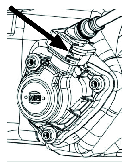 |
| Old On/Off | New On/Off | Linear | Stepped | Screw Type | Clip Type |
Clean any dirt from around the plastic sensor cover to be replaced and remove the electrical connector, being careful that nothing falls into the air chamber pushrod aperture.
! MEI sensor covers are supplied preset in the correct position however the caliper pistons need to be set to match this it is recommended that this is done with the brake removed from the vehicle.
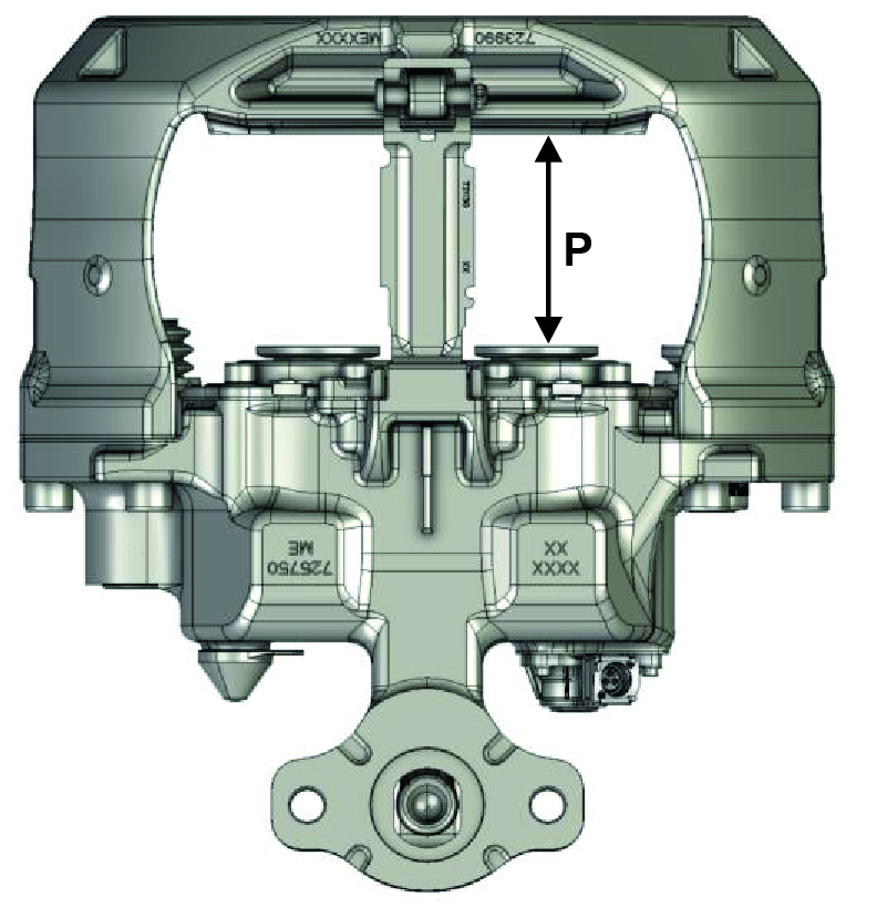
1 Adjust the tappets using a 10mm ring spanner or socket wrench on the adjuster do not exceed 25 Nm torque until a setting gap ‘P’ (see table) is achieved between right hand piston and outboard pad abutment face.
 |
Caliper Variant + Sensor Cover Variant |
Setting Gap 'P' |
Sensor Voltage |
| LNR225 + Silver Pins + White Circle / Red Block |
105 ± 0.25 mm | 0.15 V | |
| LNR225 + Silver Pins |
105 ± 0.25 mm | 1.0 V | |
| LNR225 + Gold Pins |
105 ± 0.25 mm | 0.7 V |
With the sensor cover mounting face uppermost remove the cover assembly to be replaced by loosening the 3 screws using a 4mm A/F hexagon drive and lift the cover away from the housing.

! Note the positions of the 3 plastic gears.
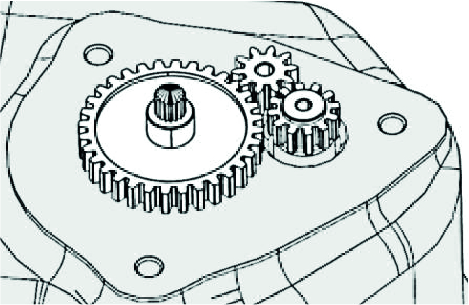
2 With the sensor cover mounting face uppermost, clean the sealing interface on the caliper housing by wiping radially away from the centre with a clean cloth, being careful not to get any dirt into the screw holes.
Replacement plastic gears are included in the service kit but may not be needed. If the gears are damaged and need to be replaced then locate them in the output shaft and housing bores, as shown below, ensuring the gear
teeth mesh correctly.

Position the new sensor cover assembly over the gears and lower it into place so that the gasket comes into full contact with the caliper housing. It may need a slight twist to align the wear sensor with the input gear and the 3 screws with the threaded holes.
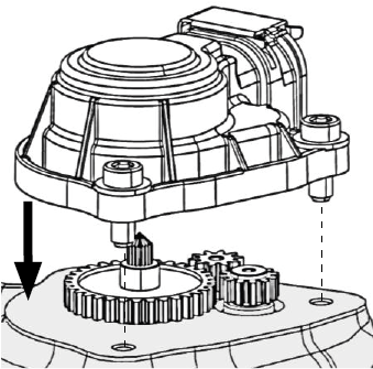
Loosely wind down the 3 screws using a 4mm A/F hexagon drive. Tighten the screws to 5- 6 Nm torque.
Refit the brake to the vehicle. Replace the pads and reset the running clearance by turning the adjuster clockwise until the pads come into contact with the disc do not exceed 25 Nm torque then turn back the adjuster 3 clicks and check the pad to disc running clearance. Replace the adjuster cap and refit the electrical connector to the sensor cover.
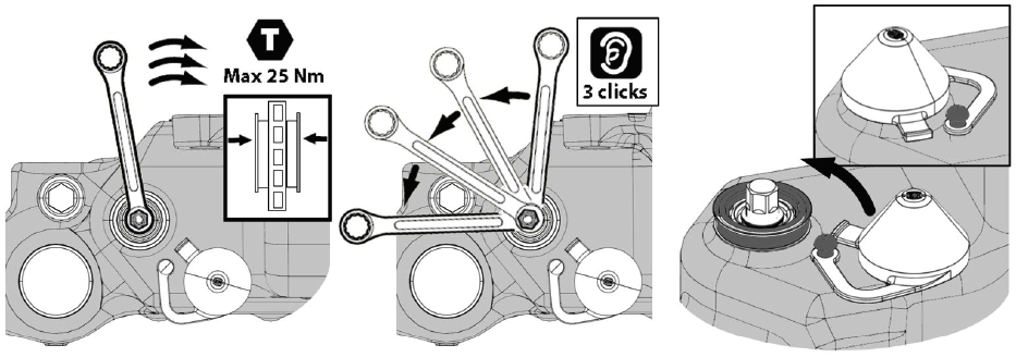
! Check the condition of the O Ring on the electrical connector. If the O Ring is damaged it can be replaced using the O Ring from the blanking plug of new sensor cover. Check there is sufficient flex in the cable of the connector to allow for movement of the brake with pad wear.
 |
 |
 |
| Screw Type | Clip Type |