Always ensure that the vehicle is securely chocked on level ground before releasing the parking brake. Cage the spring brake or use a minimum hold off pressure of 90 psi (6 bar).

Operational checks should be carried out annually or at every pad replacement. It is important to check the brake adjuster is functioning correctly and that the caliper slides smoothly over its full range of travel.
Adjuster Function
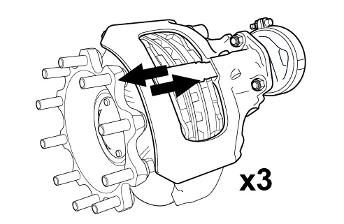
Ensure that service brake and parking brake are in the released condition – always ensure the vehicle is securely chocked before releasing the parking brake. Push and pull caliper 3 times in an axial direction to assess the running clearance between pads and disc. If the caliper does not move then check the condition of the guide sleeve bushes. Remove the adjuster cap and fit new pads. Set the clearance by turning the adjuster anti-clockwise with a suitable 10 mm ring spanner or socket wrench, and then turn clockwise until 1.3 mm running clearance has been achieved, measured between the tappet heads & inboard pad, ensuring there is no clearance at the outboard pad.
! Never exceed a maximum torque of 25 Nm in either direction, and never use power tools.
Note: When turning the adjuster anti-clockwise a noticeable clicking can be heard & felt.
 |
 |
 |
Apply the brakes 20 times with pressure of 2-3 bar. Measure the clearance between each tappet head and the inboard pad backplate – this should be measured over the whole surface of both tappet heads simultaneously using two feeler gauges at least 220 mm long. The running clearance between each tappet head and inboard pad backplate must measure between 0.6 - 1.2 mm. If the difference between the running clearance at each tappet head is more than 0.25 mm then check the condition of the guide sleeve bushes.
 |
 |
 |
If the running clearance is bigger than 1.2 mm then the adjuster must be checked as follows;
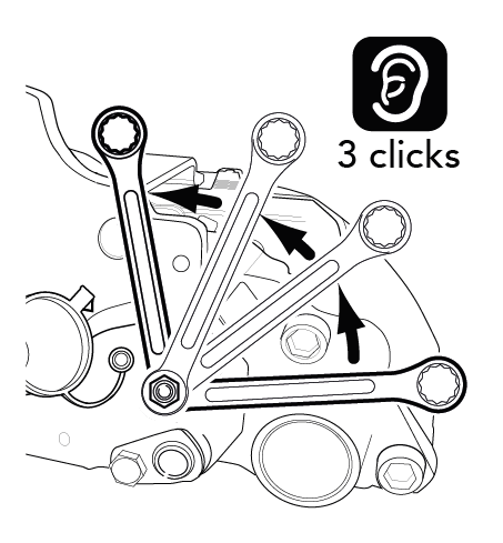
• Turn the adjuster anti-clockwise by 3 clicks to increase the running clearance.
• Position a ring spanner or socket wrench onto the adjuster as a visual aid, as shown, ensuring there is sufficient clearance for it to move freely.
• Apply the brake 5 to 10 times (with 2-3 bar pressure) and the ring spanner should turn clockwise in small increments (as viewed from the air chamber side). Note that as the number of applications increases then incremental movement of the spanner will decrease.
• If the ring spanner does not turn, or turns only with the first application, or turns forward and backward with every application, then there is a problem and the caliper must be replaced.
If the running clearance is smaller than 0.6 mm then the caliper must be checked as follows;
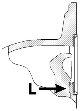
• Remove the air chamber and check that the lever is in contact against the caliper housing (see arrow “L”).
• Remove the brake pads and if necessary, remove dirt from the brake pads, carrier & caliper;
• Check the brake pads for wear from the tappet heads. If necessary replace the brake pads.
• Check for wear of the pad contact areas of the carrier and if necessary replace the carrier.
• Check the brake disc for wear or damage and if necessary replace the disc.
• Check caliper slides smoothly over its full range of travel (see Caliper Sliding check).
• Refit the brake pads and the air chamber. Repeat the adjuster function check. If the running clearance is still smaller than 0.6 mm then the caliper must be replaced.
 |
! If the running clearance is too big there is a risk of reduced brake performance and brake failure.
! If the running clearance is too small there is a risk of overheating and subsequent damage.
Note: opening the caliper or removing the adjuster will invalidate the warranty.
Caliper Sliding
Ensure that the service brake and parking brake are in the released condition – always ensure the vehicle is securely chocked before releasing the parking brake. Push and pull the caliper, by hand, in an axial direction within the running clearance between pads and disc. If, even using a high level of hand force, the caliper is not sliding then examine the guide sleeve sealing components.
! Take care not to trap fingers when sliding the caliper.
 |
The caliper must slide freely along the whole length of the guide sleeve, with movement greater than 25 mm when the pads are not present. If the caliper does not move at least 25 mm, then examine the guide sleeve sealing components.
 |
Guide Sleeve Bush
Remove the pad retainer by unscrewing the bolt. If necessary remove any pad wear indicator cable and clips (making note of the cable arrangement for re-fitting).
 |
 |
! Depending on the orientation of the caliper the brake pads could fall out when removing the pad retainer.
Remove the brake pads, and replace with a pair of new pads to locate the caliper in the correct position in relation to the carrier. If the guide sleeve bush clearance check is not taking place during a brake pad replacement, the relative positions of the assembled pads must be noted so that they can be re-assembled in the same relative positions.
Note: The easiest time to check this is when changing pads.
Fasten a magnetic dial gauge indicator to the carrier on the short guide sleeve side of the caliper and use the casting feature A on the caliper as the measurement point.

Push the caliper in the direction of the carrier and set the dial-gauge to zero. Place a suitable tool (300 mm max. length e.g. a screwdriver) centrally between the carrier and the caliper. Lever them in opposite directions, using light hand force, to read the maximum value of the bush clearance on the dial gauge.
If the measured bush clearance exceeds 2mm then the guide sleeve bushes need to be replaced using the relevant MEI service kit.
If the clearance check is not taking place during a brake pad replacement, the new pads should be removed and the original brake pads fitted in their previously noted positions. Adjust the running clearance by turning the adjuster clockwise until the pads come into contact with the disc – do not exceed 25 Nm whilst doing this. Turn the adjuster back anti-clockwise 3 clicks and check the pad-to-disc running clearance. Re-fit the adjuster cap, pad retainer and any in-pad wear sensor components.
Sealing Components
Guide Sleeve Boots
Inspect the protective caps for correct fitment and any signs of damage. Remove the brake pads to inspect the condition of the guide sleeve boots. If the guide sleeve boots or caps are damaged replace them using the relevant MEI service kit.
Note: the boot and cap is common for both long and short guide sleeves.

Tappet Boots
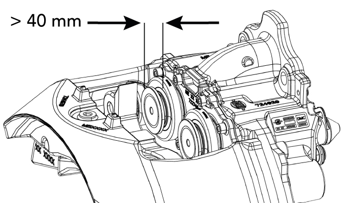
With the brake pads removed, adjust the tappets using a ring spanner or socket wrench on the adjuster until the boots are clearly visible. The tappets must not be extended more than 40 mm.
 |
 |
 |
Inspect the condition of the tappet boots. If the tappet boots are damaged replace them using the relevant MEI service kit.
Note: A little rotational free play of the tappet head is normal and a good indication that the sealing is intact.
Adjuster Cap
Check for correct fitment and condition of the adjuster cap.
If the cap is damaged or missing replace the adjuster cap using the relevant MEI service kit.
