Guide Sleeve Seal and Bush
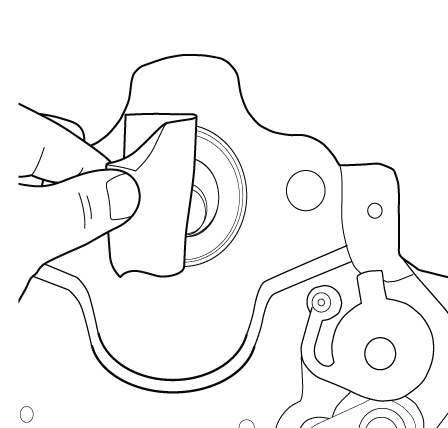
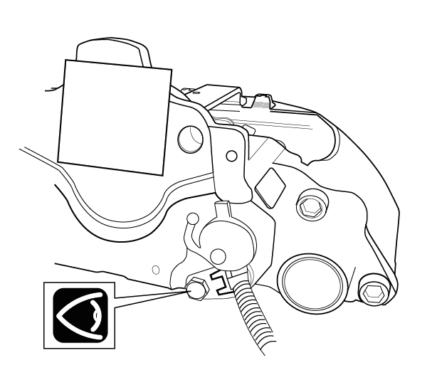
1. Remove the brake pads as described in the PAD REPLACEMENT section. Remove the air chamber from the caliper in line with the vehicle manufacturer’s recommendations. If fitted, remove the electronic pad wear sensor from the housing by unscrewing the M10 bolt and carefully levering out the sensor, as this will need to be refitted the sensor, as this will need to be refitted when the caliper is refitted to the axle.
! Be careful locating the removed pad wear sensor so that it does not get damaged.
Note: Cover the exposed air chamber & wear sensor apertures with adhesive tape to prevent debris entering. Support the air chamber so that it does not interfere with brake removal or cause strain on the air hose.
It is recommended to remove the caliper and carrier from the axle, but refer to vehicle manufacturer’s recommendations for specific guidance.
 |
 |
 |
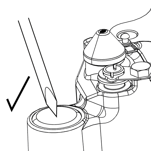
2. Pierce the middle of the protective cap using a suitable tool. Do not drive the tool between caliper bore and cap, as this might damage the caliper bore.
 |
 |
3. Remove the guide sleeve protective cap by inserting a suitable tool into the created hole and levering it out.
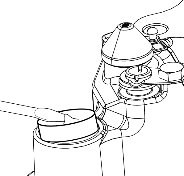
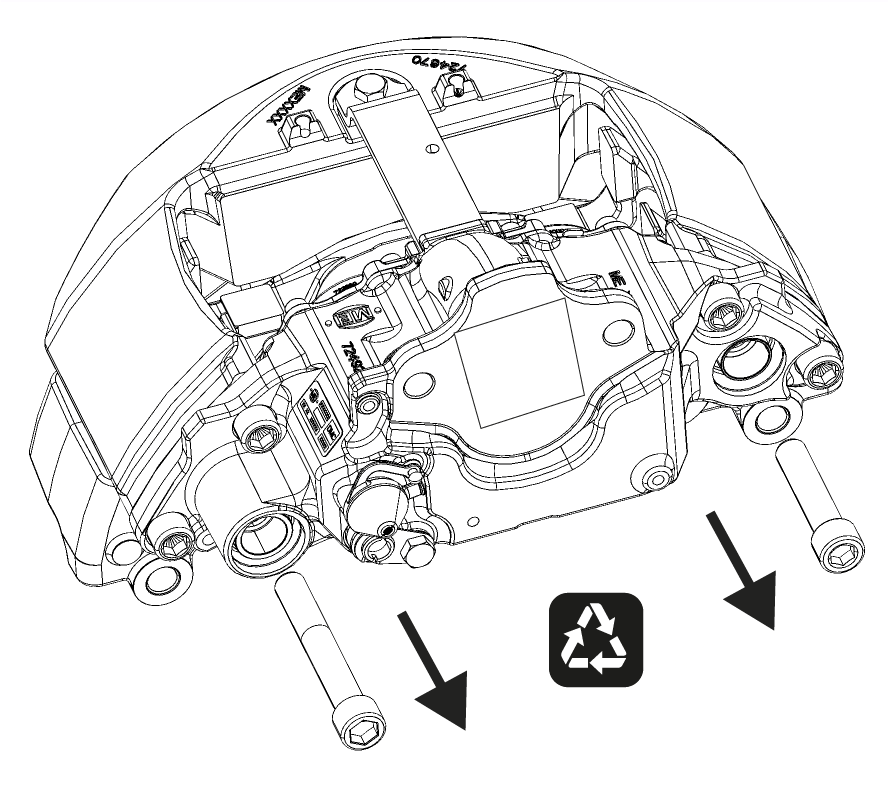
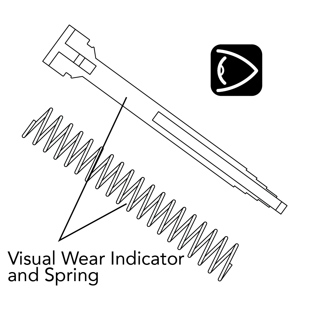
4. Remove and discard the guide sleeve bolts and remove the caliper from the carrier. Ensure the carrier is securely located to resist the bolt torque, at a location close to the bolt being loosened, to prevent damaging the carrier. If a visual wear indicator and spring are fitted retain these so that they can be refitted.
 |
 |
 |
! Before removing the guide sleeve bolts ensure that the caliper cannot move or fall causing injury.
Note: If necessary carefully release the guide sleeves from their location on the carrier using a rubber hammer.
5. Only use genuine MEI replacement parts – see MEI website for further information (www.meibrakes.com).
Note: The MEI brake assembly number – from the identification plate located on top of the brake housing – should be referenced in order to obtain the correct repair kit.

6. Pull the guide sleeve boots from the housing retainers and remove and discard the guide sleeves and boots. Remove the guide sleeve boot retainers using a suitable lever, taking care not to
damage the bores. Check the inside area of the caliper bores. In case of damage or excessive corrosion the
caliper must be replaced.

7. To extract the two round guide sleeve bushes, use tool combination M10, M24 & M25 from the MEI brake tool kit (ref.9K1010 or equivalent). Note that this can be done without removing the bridge from the housing.
! Note that the use of impact drivers / air wrenches is not permitted with the service tools.
Clean the guide sleeve bushes and the tool contact areas (arrows J and K), then position the tool as shown. M24 may need to be orientated so that the tool clears the profile of the housing, and ensure M25 seats correctly into the bush. Extract both bushes by turning the bolt (M10) using a 24 A/F ring spanner, using another 24 A/F ring spanner to prevent M25 rotating. Make sure that M24 remains seated squarely on the caliper housing surface and does not tilt during extraction.

| Tool Positioned to Extract Round Bushes |
Round Bushes Extracted |
Tool Incorrectly Positioned |
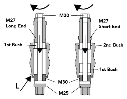
8. To fit new round guide sleeve bushes (ref. MEI kit 9R0250 / 9R0255) use tool combination M10, M25, M27 & M30. Fit the 1st bush onto the long end of M27, then assemble the prepared parts through the caliper bore from opposite ends and screw M10 into M25 by hand until it stops. Check that M30 is seated squarely (arrow L), with the annular groove facing the bore, then pull the bush into the bore by turning M10 using a 24 A/F ring spanner until it stops, using another 24 A/F ring spanner to prevent M25 rotating. Repeat the process with the 2nd bush on the short end of M27.
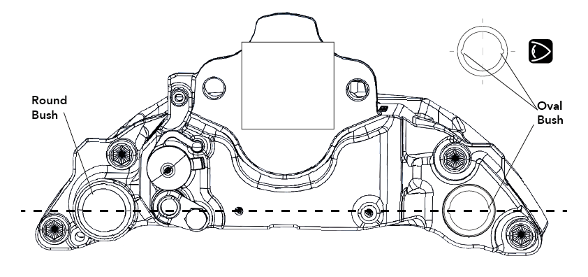
10. To extract the thicker oval guide sleeve bush, use tool combination M10, M24 & M26 from the MEI brake tool kit (ref. 9K1010 or equivalent). Note that this can be done without removing the bridge. For radial brakes (NR225) there are 2 oval bushes, but both can be extracted simultaneously using the same method as for a single oval bush. Prior to removal make a note of the angular orientation of the oval bush this is indicated by 2 notches in the bush which will be aligned with the horizontal plane between the guide sleeve bores.
10. Clean the guide sleeve bushes and the tool contact areas (arrows M and N), then position the tool as shown. M24 may need to be orientated so that the tool clears the profile of the housing, and ensure M26 seats correctly into the bush. Extract the bush by turning the bolt (M10) using a 24 A/F ring spanner, using another 24 A/F ring spanner to prevent M26 rotating. Make sure that M24 remains seated squarely on the caliper housing surface and does not tilt during extraction.
Note: Apply grease to the bolt thread (M10) to reduce the effort required to remove the bush.
Note: Ensure M10 is rotated and M25 or M26 remains stationary to prevent damaging the tools.

| Tool Positioned to Extract Oval Bushes |
Oval Bushes Extracted |
Tool Incorrectly Positioned |
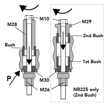
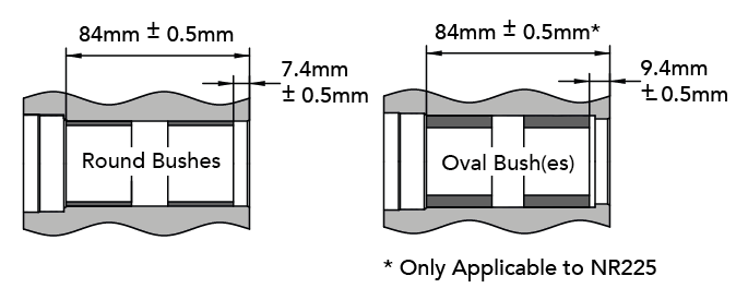
11. To fit new oval guide sleeve bushes (ref. MEI kit 9R0250 / 9R0255) use tool combination M10, M26, M28 & M30 (& M29 for radial brakes). Fit new oval bush onto M28, then assemble the prepared parts through the caliper bore from opposite ends and screw M10 into M26 by hand until it stops, ensuring the 2 notches in the bush are aligned with the horizontal plane between the guide sleeve bores. Check that M30 is seated squarely into the housing bore (arrow P), with the annular groove facing away from the bore, then pull the bush into the bore by turning M10 using a 24 A/F ring spanner until it stops, using another 24 A/F ring spanner to prevent M26 rotating. Remove the tools and check that the angular orientation of the oval bush is correct by the position of the two notches these should be aligned with the horizontal plane between the guide sleeve bores.
For radial brakes (NR225) repeat the process with the 2nd oval bush fitted onto M29 instead of M28.
12. After assembling the new bushes check that they are fitted to the correct depth.
13. To fit new guide sleeve boot retainers use tool combination M10, M25, M30 & M31. Fit the boot retainer into the recess of M30, then assemble the prepared parts through the caliper bore from opposite ends and screw M10 into M25 by hand until it stops. Check that the face of M30 is parallel to the housing (arrow Q), then pull the boot retainer into the bore by turning M10 using a 24 A/F ring spanner until it stops.
! Do not apply excessive force when pulling the retainer into the bore as this may damage to the retainer.
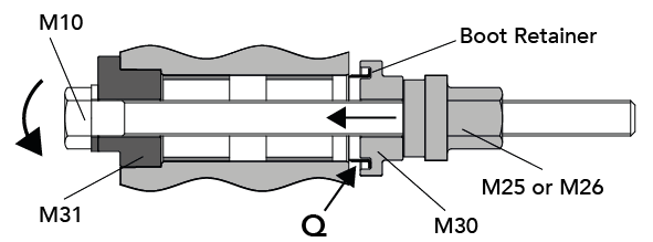
14. Repeat the process with the boot retainer in the other guide sleeve bore for the axial brakes, with a short guide sleeve, M29 can be used as a spacer to prevent M10 contacting the bridge.

15. After assembling the new boot retainers check that they are fitted to the correct depth. Grease all of the bushes with WHITE grease using the grease provided in the MEI repair kit (ref. 5F1500).

16. To fit a new guide sleeve boot (ref. MEI kit 9R0250 / 9R0255 ), first fit the boot over the retainer in the housing, as shown below, then rotate and gently pull the boot to check it is fully engaged all around the retainer. Note that the guide sleeve boot is symmetrical and fits either way round, and is common to both guide sleeves.

Note: Apply a little grease to the sealing beads at both ends of the boot to help them slide into the grooves
Note: Be careful not to nip the boot between the guide sleeve and the retainer.
Insert the relevant new guide sleeve through the outboard end of the boot, and gently push the sleeve through so that it engages with the guide sleeve bush. Roll the outboard sealing bead over into the groove, all around the guide sleeve, ensuring the sealing bead is not twisted. Slide the guide sleeve in and out of the housing by approx. 25 mm to check that both sealing beads are correctly engaged. Repeat for the second guide sleeve boot and guide sleeve.
17.
Ensure that the carrier threads are clean and dry (free of lubrication). Clean the guide sleeve contact areas in the carrier and check the pad abutment surfaces for damage or excessive corrosion if these are damaged then the carrier should be replaced.
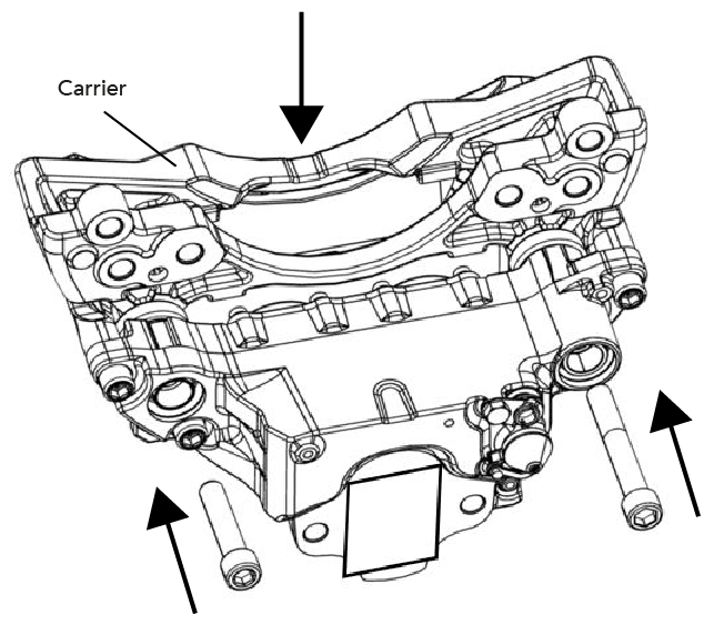
Lower the carrier on to the caliper and locate the new bolts though the guide sleeves into the carrier. If a visual wear indicator is fitted to the brake then ensure this is in place before fitting the guide sleeve bolts, locating the visual wear indicator and spring between the carrier and housing as shown below.

Ensure the carrier is securely located to resist the bolt torque, at a location close to the bolt being tightened to prevent damaging the carrier. Tighten the bolts as specified below and check that the caliper slides easily on the guide sleeves.
• Long guide sleeve bolt (120 mm) : 80 Nm, then tighten by a further 120°
• Short guide sleeve bolt (80 mm) : 80 Nm, then tighten by a further 90°
 |
 |
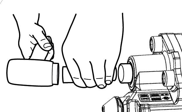
18. To fit a new guide sleeve end cap (ref. MEI kit 9R0250 / 9R0255 ) use tools M32 & M33 from the MEI brake tool kit. The protective cap and bore must be clean and free from lubrication.
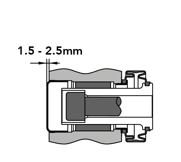
Use a copper head mallet with tools M32 & M33 to press the guide sleeve end cap into the guide sleeve bore, ensuring it is seated squarely, until the cap protrudes 1.5 to 2.5 mm from the cast boss. Tool M33 may need to be rotated so that the cut away section provides clearance to the housing features. Repeat for the second guide sleeve end cap. Note that the end cap and fitting height is common to both guide sleeves.
 |
 |
 |
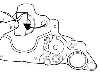
Note: Fitting the protective cap can only be done after the caliper has been fully bolted to the carrier and the guide sleeve boot must be in a compressed condition otherwise the caliper movement may be limited
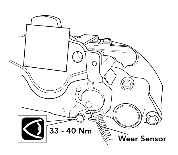
19. Replace the brake on the axle in line with the vehicle manufacturer’s recommendations. Refit the brake pads as described in the PAD REPLACEMENT section. If applicable, refit the electronic pad wear sensor to the housing, removing any adhesive tape, and tighten the M10 bolt to 33 40 Nm. Prior to fitment check that the 2 O rings and the plunger of the pad wear sensor are free from damage and, if needed, apply a little grease (ref. 5F1500) to the O rings to ease assembly.

20. Remove any adhesive tape over the brake aperture and refit the air chamber, tightening the nuts to 180-210 Nm, or in line with the vehicle manufacturer’s recommendations.
 |
 |
 |
Tappet Boots
Replacement of the tappet heads & boots (ref. MEI kit 9R0450) is easiest with the brake removed from, the vehicle. No special tools are required, but MEI tool kit (ref. 5K0010), if available, can be used for fitting the tappet heads.
! Note that the use of impact drivers / air wrenches is not permitted with the service tools.
1. Remove the brake pads as described in the PAD REPLACEMENT section. Using a 10mm ring spanner or socket wrench, adjust the pistons forward to approximately 30mm from the piston housing, so that the tappet heads are easily accessible (do not exceed 25 Nm torque). Pull each tappet boot off the retainer on the piston housing, and stretch them over the tappet head to completely remove from the caliper, and discard. Check the tappet heads for damage or excessive corrosion. If they do not look suitable for further service then replace the tappet heads, as well as the tappet boots as described below.
! Note that it is not necessary to remove the tappet heads if only the tappet boots need replacing
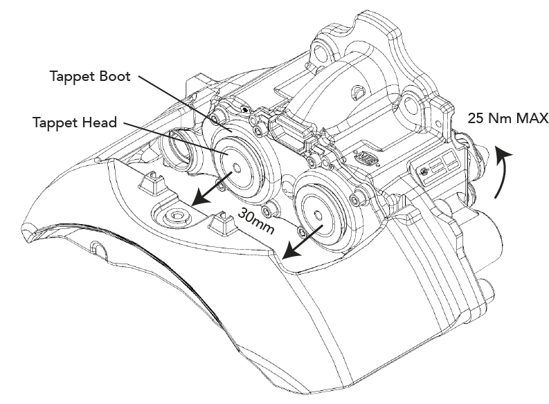
2. Using a copper head mallet knock the tappet head off the piston shaft, being careful not to damage the piston, then remove the tappet bush from the end of the piston. Clean and check the pistons and the boot retainers for damage or corrosion. The pistons, secondary seals and piston housing cannot be replaced and if damaged, or there are signs of water ingress, then the caliper must be replaced.
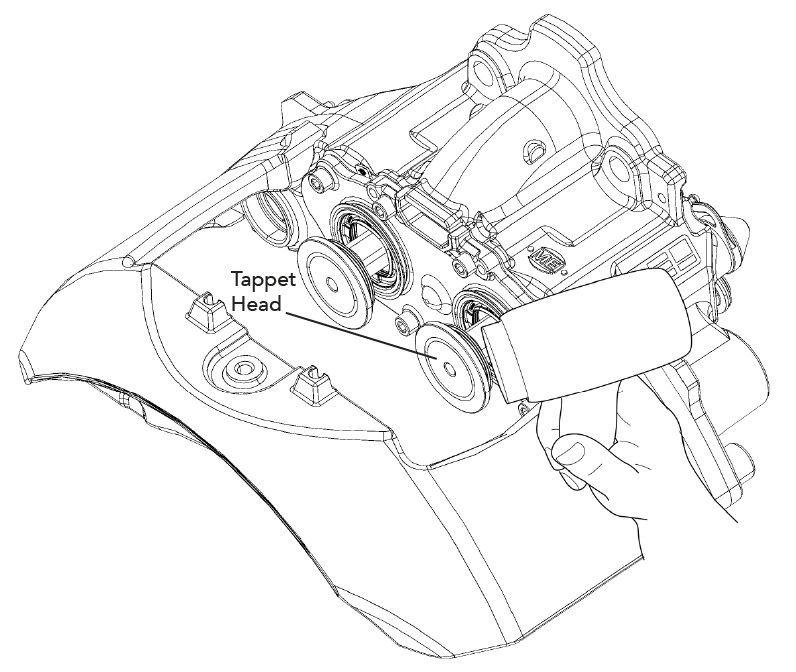
! Do not use excessive force to remove the tappet heads – this may damage the piston shafts. Opening or dismantling the caliper any further will invalidate the warranty.
Lubricate the piston shafts with WHITE grease (ref. 5F1500).
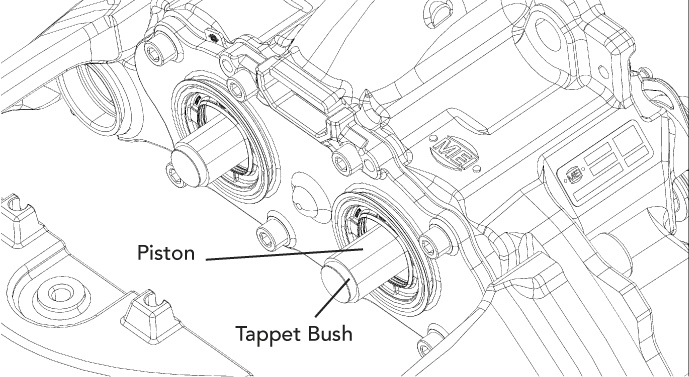
3. Ensure that the old tappet bush is removed and then fit a new tappet bush by hand. Locate the new tappet head on to the piston shaft and tap lightly with a copper head mallet to secure it to the piston. Repeat for the second tappet head. If MEI brake tool kit (ref. 5K0010 or equivalent) is available then tools M03, M04, M05 & M06 can be used to fit the tappet head on to the piston in the same way as for L-series brakes. After the new tappet heads are fitted carefully stretch the new tappet boot over the tappet head, as shown below, without the sealing beads engaged, ensuring the boot is the correct way round.

Fit the larger diameter boot sealing bead over the piston housing retainer, ensuring that the sealing bead is seated correctly and fully engaged all around the retainer.
Tip: Apply a little grease to the sealing beads at both ends of the boot to help them slide into the grooves
4. Rotate the boot around on the retainer so that the pull-tab is easily accessible. Fit the smaller diameter boot sealing bead into the tappet head groove, ensuring that the sealing bead is seated correctly and fully engaged all around the groove. Repeat for the second tappet boot.
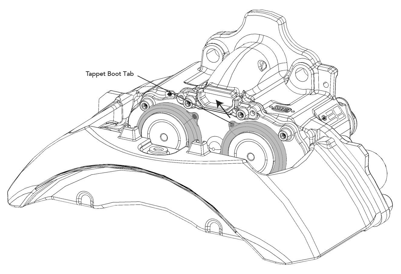
After assembly check that the tappet boots are securely attached by pulling them lightly by hand, and check that the tappet heads are free to rotate slightly in each direction – taking care not to over-stress the tappet boots.
Rewind the tappets using a 10mm ring spanner or socket wrench on the adjuster until the tappet heads are back in the start position (do not exceed 25 Nm torque). Gently pull the tab to release any excess air trapped in the tappet boots.
If the caliper has been removed from the vehicle then replace the brake on the axle in line with the vehicle manufacturer’s recommendations. Refit the brake pads as described in the PAD REPLACEMENT section.
! If the brake is removed from the vehicle then new axle mounting bolts should be used for re-installation
Pad Replacement
Remove the wheel (referring to the vehicle manufacturer’s recommendations). If necessary remove any pad wear warning indicator (PWWI) cable & clips (note the cable arrangement for fitting a new PWWI). Remove the pad retainer by removing the hexagon head bolt.
! Depending on the orientation of the caliper the brake pads could fall out when removing the pad retainer.
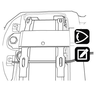 |
 |
 |
Remove the adjuster cap. Fully wind back the tappets, using a 10mm ring spanner or socket wrench, by turning the adjuster anti-clockwise as viewed from air chamber side.
! Never exceed a maximum torque of 25 Nm in either direction, and never use power tools.
Note: when turning anti-clockwise a noticeable clicking can be heard & felt.

Remove the worn brake pads and then check the caliper sliding.
Check the rubber boots and replace if necessary. Clean the pad abutments of the carrier if required, taking care not to damage the rubber boots. Check the brake disc thickness and for signs of heavy grooving, cracking or corrosion.
Fully wind back the tappets using a 10mm ring spanner or socket wrench by turning the adjuster anti-clockwise as viewed from air chamber side and fit the new brake pads.
! You must always replace the brake pads on both brakes across an axle.
! Ensure old brake pads are disposed of in accordance with local environmental regulations.
| Inboard Pad | Outboard Pad |
 |
 |
Turn the adjuster clockwise until the pads come into contact with the disc – do not exceed 25 Nm torque. Turn back the adjuster anti-clockwise 3 clicks and check the pad-to-disc running clearance – there should be free rotation of the disc. Refit the adjuster cap.
 |
 |
 |
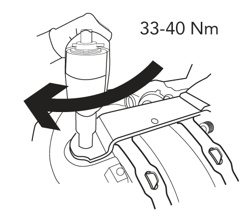
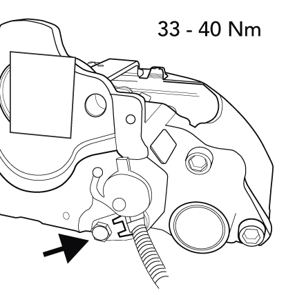
Locate the new pad retainer in the slot in the caliper and depress to enable fitment of the hexagon head bolt. Tighten the bolt to 33-40 Nm. Reconnect the pad wear sensor (where applicable), tightening the hexagon head bolt to 33-40 Nm.
Ensure the pad wear sensor is clean and free from dirt and moisture.
 |
 |
If applicable, fit a new pad wear warning indicator (PWWI) cable & clips in the same orientation as they were removed.
 |
 |
Replace the wheel in line with the vehicle manufacturer’s recommendations. Uncage the spring brake and apply the parking brake prior to removing the chocks from the vehicle. After releasing the parking brake, apply the brake 10 times then road test the vehicle to bed the pads and check the brake performance.
! Remember that there may be a lower performance during the bedding-in phase of the new brake pads.