Please visit our youtube channel for a full range of caliper service videos.
Guide Sleeve Seal and Bush
The instructions below can be downloaded via this link: Download
1. Remove the brake pads as described in the PAD REPLACEMENT section above. Remove the air chamber from the caliper in line with the vehicle manufacturer’s recommendations. If fitted, remove pad wear sensor cable from the chain cover.
! Do not touch the electrical contact points – there is risk of static discharge.
Note: Cover the exposed air chamber & wear sensor apertures with adhesive tape to prevent debris entering.
‘Support the air chamber so that it does not interfere with brake removal or cause strain on the air hose.
In some cases it may be necessary to remove the caliper and the carrier from the axle – refer to vehicle manufacturer’s recommendations.

2. Pierce the middle of the protective cap using a suitable tool. Do not drive the tool between caliper bore and cap, as this might damage the caliper bore.
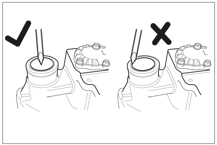
3. Remove the guide sleeve protective cap by inserting a suitable tool into the created hole and levering it out.

4. The longer protective cap (Type C) should be removed from the side and in an upward direction. Do not hit the protective cap in the direction of the caliper as this might damage the caliper.
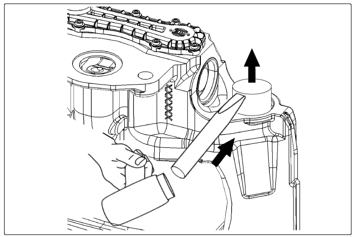
5. Remove and discard the guide sleeve bolts and remove the caliper from the carrier. If the brake is removed from the vehicle ensure the carrier is securely located to resist the bolt torque, at a location close to the bolt being tightened, to prevent damaging the carrier.
! Before removing the guide sleeve bolts ensure that the caliper cannot move or fall causing injury.
Note: If necessary carefully release the guide sleeves from their location on the carrier using a rubber hammer.

6. Only use genuine MEI replacement parts – see MEI website for further information (www.meibrakes.com).
Note: The MEI brake assembly number – from the identification plate located on top of the brake housing – should be referenced in order to obtain the correct repair kit.

7. Remove and discard the guide sleeves and plastic washer and ease out guide sleeve boot with a suitable tool (e.g. screwdriver). Check the inside area of the caliper bores and seal interfaces. In case of damage or excessive corrosion the caliper must be replaced.

8. To extract the long guide sleeve brass bush, use tool combination M10, M11 & M13 from the MEI brake tool kit (ref. 5K0010 or equivalent).
! The use of impact drivers / air wrenches is not permitted with the service tools.
Clean the brass bush and the tool contact areas (arrows J and K), then position the tool as shown. Ensure M11 seats correctly into the brass bush. Extract the brass bush by turning the bolt (M10) using a 24 A/F ring spanner, using another 24 A/F ring spanner to prevent M11 rotating. Make sure that M13 remains seated squarely on the caliper housing surface and does not tilt during extraction.

9. To fit a new brass bush (ref. MEI kit 5R0200 / 5R0205) use tool combination M10, M11, M14 & M15. First screw M11 onto the bolt (M10) and then fit M14 onto M10. Push the new brass bush onto M15, then assemble the prepared parts through the caliper bore from opposite ends and screw M10 into M15 by hand until it stops. Check that M14 is seated squarely on the surface (arrow L), then pull the brass bush into the bore by turning M11 until it stops.

10. To prevent axial movement of the brass bush it must be “staked” into the bore (arrow M). The hexagonal bolt of tool M15 (arrow N) must be screwed in up to its stop to deform the brass bush into place. Wind back the hexagonal bolt (arrow N) of tool M15 approximately 15 mm. Slacken off nut M11 and rotate tool M15 approximately 60°. Re-tighten nut M11 and screw in M15 to repeat the “staking” process. The brass bush is now secured against axial movement. The hexagonal bolt of tool M15 must be screwed out again approximately 15mm before removing the tool and checking the contact area of the brass bush and removing any burrs (if necessary). Grease the brass bush with WHITE grease (ref. 5F1500) provided in the MEI repair kit.
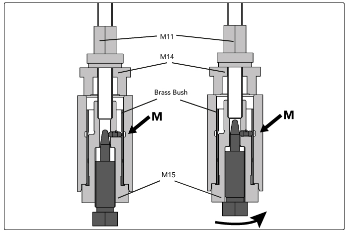
11. To extract the short guide sleeve rubber bush (ref. MEI kit 5R0200) use tool combination M10, M12, M16 & M17 from the MEI brake tool kit (ref. 5K0010 or equivalent). Position the tool as shown and hand tighten M12 ensuring M16 seats correctly into the steel ring. Extract the rubber bush and steel ring by turning the bolt (M10) using a 24 A/F ring spanner, using another 24 A/F ring spanner to prevent M12 rotating.
Note: Apply grease to the bolt thread (M10) to reduce the effort required to remove the bush.
Note: Ensure M10 is rotated and M12 remains stationary to prevent damaging the tools.
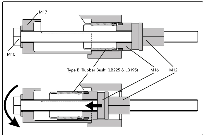
12. To fit a new short guide sleeve rubber bush (ref. MEI kit 5R0200) use tool combination M10, M12, M16, M18 & M19. The grub screw on M19 should be wound in so that it does not contact the caliper surface, and M19 is coaxial with the guide sleeve bore. Push the new rubber bush into tool M18. Assemble the prepared parts through the caliper bore from opposite ends and screw M12 onto M10 by hand until it stops. Take care not to tilt the rubber bush when winding it in. Pull the rubber bush into the bore until it stops by turning the bolt (M10) using a 24 mm A/F spanner, using another 24 A/F ring spanner to prevent M12 rotating. Remove the tool and check that therubber bush metal ring does not move.
Note: When checking the metal ring ensure that the sealing lip is not damaged.
Grease the rubber bush with WHITE grease (ref. 5F1500) provided in the MEI repair kit.

13. To extract the short guide sleeve plain bush (ref. MEI kit 5R0205) use tool combination M10, M12 & M17. Position the tool as shown and hand tighten M12 ensuring it seats correctly into the bush. Extract the bush by turning the bolt (M10) using a 24 A/F ring spanner, whilst using another 24 A/F ring spanner to prevent M12 rotating.
Note: Apply grease to the bolt thread (M10) to reduce the effort required to remove the bush.
Note: Ensure M10 is rotated and M12 remains stationary to prevent damaging the tools.
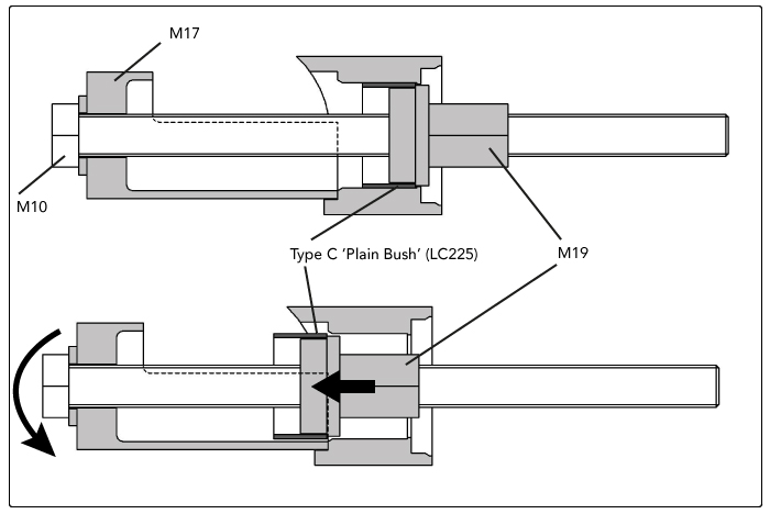
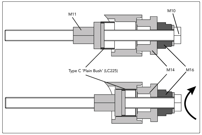
14. To fit a new short guide sleeve plain bush (ref. MEI kit 5R0205) use tool combination M10, M11, M14 & M16. Note that M16 is used as a spacer in order to provide clearance for M10 with the housing. Fit the new plain bush onto tool M11. Assemble the prepared parts through the caliper bore from opposite ends and screw M11 onto M10 by hand until it stops. Take care not to tilt the plain bush when winding it in. Pull the plain bush into the bore until it stops by turning the bolt (M10) using a 24 mm A/F spanner, using another 24 A/F ring spanner to prevent M11 rotating. Grease the plain bush with WHITE grease (ref. 5F1500) provided in the MEI repair kit.
Note: The plain bush is round & does not require staking to prevent it rotating, unlike alternative ‘non-round’ bushes.
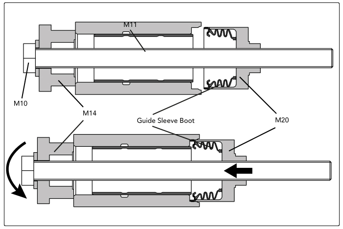
15. To fit a new guide sleeve boot (ref. MEI kit 5R0200 / 5R0205) for the long guide sleeve use tool combination M10, M14 & M20. The assembly process for the guide sleeve boot for the short guide sleeve (for MEI kit 5R0205) is the same method as for the long guide sleeve but add tool M13 between M10 and M14 to act as a spacer. Clean the seal interface of the caliper bore (arrow Q) – in case of damage or excessive corrosion the caliper must be replaced. Fit the new guide sleeve boot into tool M20, ensuring that the rubber bellows sit inside the tool (arrow R).

16. Assemble the prepared parts, with the new guide sleeve boot fitted into M20, through the caliper bore from opposite ends and screw M20 onto M10 by hand until it stops. Take care not to tilt the guide sleeve boot when winding it in.
Pull the guide sleeve boot into the bore until it stops by turning the bolt (M10) using a 24 mm A/F spanner, using another 24 A/F ring spanner to prevent M20 rotating. Be careful not to damage the boot by over-tightening – apply 8 Nm maximum torque. Remove the tools and check for correct fitment of the guide sleeve boot by gently pulling the boot away from the bore and checking it does not move.
17. Slide the new guide sleeves into the bushes in the directions indicated;
Type B (LB225, LB195, LV225 & LA225) = short guide sleeve rubber bush without second boot on caliper
Type C (LC225) = short guide sleeve plain bush with second boot on caliper

18. Locate the boot into the sealing groove in the guide sleeve. Ensure the boot seats correctly all around the sleeve and is not twisted. Locate the plastic washer over the boot to retain it in the sealing groove in the guide sleeve. Ensure the washer is in the correct orientation, with the flat face of the washer facing towards the brake carrier.

Ensure that the carrier threads are clean and dry (free of lubrication and residuals of pre-applied adhesive). Lift the caliper over the carrier – using suitable lifting equipment for the caliper – and locate the bolts into the carrier.
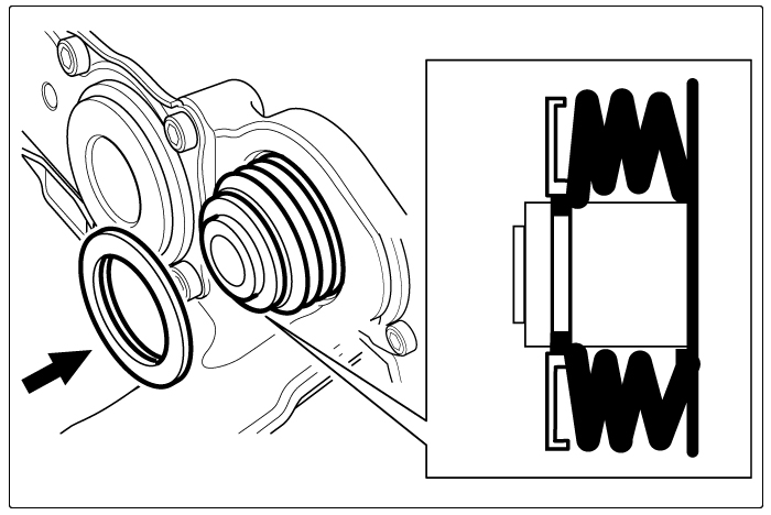
19. Ensure the correct new bolts are used for each guide sleeve – the long guide sleeve bolt has a pre-applied adhesive.

20. If the caliper is being fitted away from the vehicle ensure the carrier is securely located to resist the bolt torque. This should be at a location close to the bolt being tightened to prevent damage to the carrier. Tighten both bolts to 180 Nm, then tighten by a further 90° and check that the caliper slides easily on the guide sleeves.
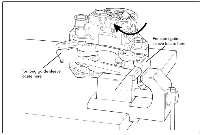
21. To fit a new guide caps (ref. MEI kit 5R0200 / 5R0205) use tools M21, M22 & M23 from the MEI brake tool kit (ref. 5K0010 or equivalent). The protective cap and bore must be clean and free from lubrication.
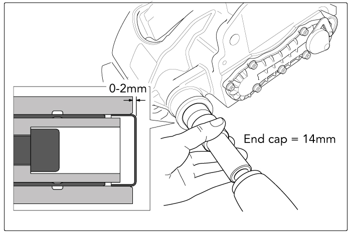
Use tool combination M21 & M22 to press the protective cap (14mm) into the long guide sleeve bore, ensuring it is seated squarely until the cap protrudes 0 to 2 mm from the cast boss.
For LC225 calipers with the Type C bush (ref. MEI kit 5R0205), use tool combination M21 & M23 to press the longer protective cap (25mm) into the short guide sleeve bore, ensuring it is seated squarely until the cap protrudes 15 to 16 mm from the cast boss.
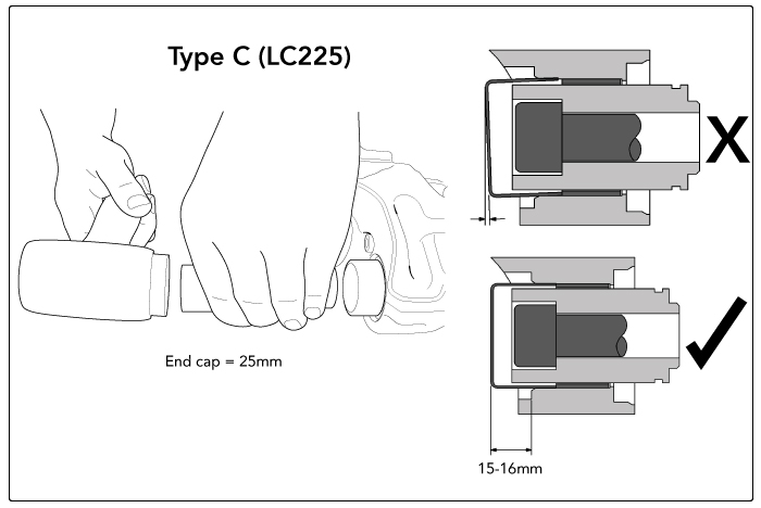
Note: Fitting the protective cap can only be done after the caliper has been fully bolted to the carrier. The guide sleeve boot must be in a compressed condition otherwise the caliper movement may be limited.
22. Replace the brake on the axle in line with the vehicle manufacturer’s recommendations. Refit the brake pads as described in the PAD REPLACEMENT section above. If applicable, replace the pad wear sensor cable connector to the chain cover. Remove any tape over the brake aperture and refit the air chamber in line with the vehicle manufacturer’s recommendations.
Tappet Boots
Replacement of the tappet boot seal assemblies (ref. MEI kit 5R0400 & 5R0405) can be done with the brake fitted to, or removed from, the vehicle using the MEI brake tool kit (ref. 5K0010 or equivalent).
! The use of impact drivers / air wrenches is not permitted with the service tools.
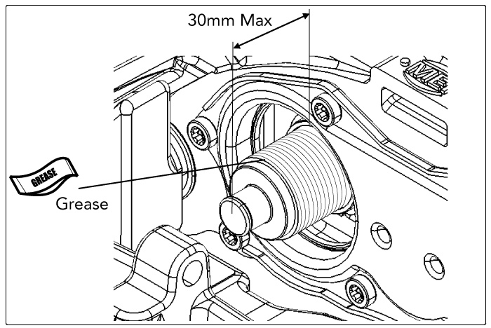
1. Remove the brake pads. Adjust the tappets forwards using a 10mm ring spanner or socket wrench on the adjuster (do not exceed 25 Nm torque) until the tappet boots are easily accessible. The tappets must not be extended more than 30 mm from the caliper face to ensure the pistons remain synchronised. With a suitable lever (e.g. screwdriver) carefully prise the tappet boot out. Take care not to damage the sealing surface on the caliper cover plate.
Note: as the tappet boot is being replaced it may aid visibility and access to cut the rubber material away.
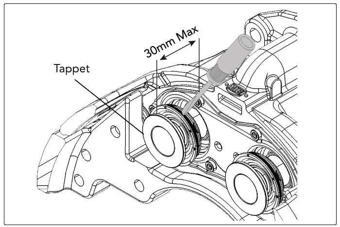
2. Position the forked wedge tool (M01) between the threaded piston and the tappet boot seal assembly with the stepped side towards the tappet boot. Carefully drive it down with a hammer to release the tappet boot seal assembly from the threaded piston. Keep the tool perpendicular to the piston – do not lever the tappet or damage the piston thread.

3. Remove the tappet bush from the end of the threaded piston. Clean and check the cover plate sealing face and the threaded pistons for damage or corrosion. The pistons and cover plate cannot be replaced and if damaged the caliper should be replaced.
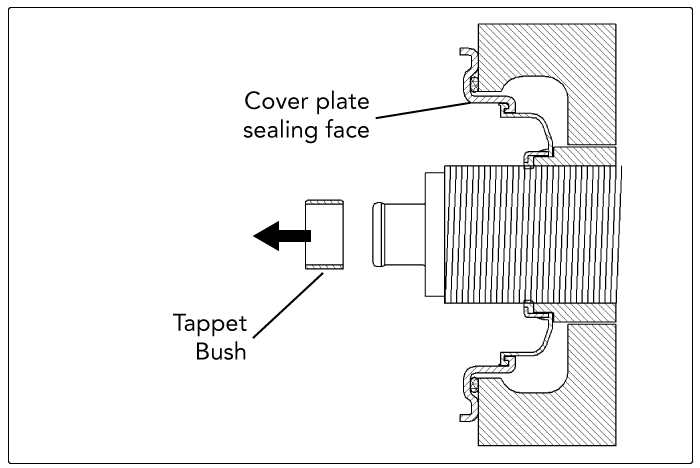
4. Wind back the threaded pistons using a 10mm ring spanner or socket wrench on the adjuster (do not exceed 25 Nm torque). Clean the area of the inner boot and carefully remove the inner boot using a suitable lever (e.g. screwdriver). Take care not to damage the sealing face on the caliper cover plate.
! Opening or dismantling the caliper any further will invalidate the warranty.
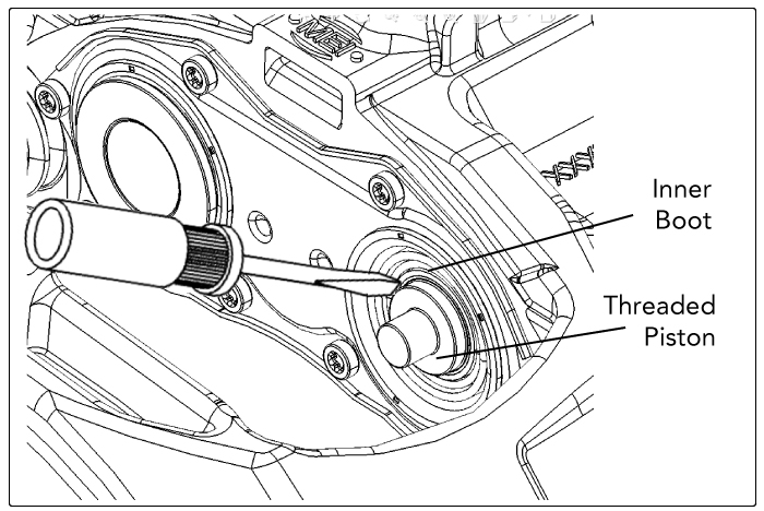
5. Wind out the threaded pistons using a 10mm ring spanner or socket wrench (do not exceed 25 Nm torque) to a maximum extension of 30 mm. Check the pistons for damage or corrosion. If there are signs of water ingress beyond the inner boots the caliper must be replaced. Lubricate the piston threads with WHITE grease (ref. 5F1500). Fully wind back the pistons and fit new inner boots over the threaded pistons carefully pushing them into position in the cover plate.
6. Ensure that the old tappet bush is removed. Position tool combination M02 & M03 over the boss of the threaded piston and wind out until M03 touches the brake disc. If the caliper is removed from the vehicle add tool M04 (between M02 & M03) and wind out until M03 touches the outboard pad abutment face of the caliper.

7. Press the inner boot over the threaded piston. Use a 27mm A/F spanner to turn M03 against the brake disc until it stops whilst stabilising M02 using a second spanner. Remove the tool and repeat for the second piston. Check for correct fitment of the inner boots: wind out the threaded pistons approx. 10mm by turning the adjuster with a 10 mm ring spanner. Check that the inner boots do not rotate with the threaded pistons. If the inner boot rotates, then the boot must be removed and the procedure repeated using a new inner boot.
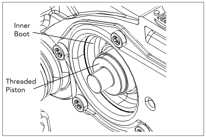
8. Clean and check the cover plate sealing face and the threaded pistons for damage or corrosion – these cannot be replaced and if damaged the caliper must be replaced. Lubricate the inner abutment face of both tappet heads with BLACK grease (ref. 5F1505) being careful not to transfer the grease to other components.
! Only use the correct grease provided in the MEI repair kit.

9. Fully wind back the threaded pistons using a 10mm ring spanner on the adjuster until they stop – do not exceed 25 Nm torque – and then wind forward one full turn. Fit a new tappet bush onto the boss of both of the threaded pistons. Fit the new tappet boot seal assemblies over the tappet bushes on the threaded pistons, pushing them into position. To complete the fitment of the tappet boot seal assemblies, use tool combination M03, M05 & M06 for fitment on the vehicle, adding tool M04 (between M03 & M05) if the brake is removed from the vehicle.
! Tool M07 in MEI tool kit 5K0010 is not required for MEI calipers.

10. Position tool combination M03, M05 & M06 so that the closed side of M06 touches the brake disc. Wind out M03 using a spanner to press the tappet boot seal assembly until it stops.

11. If the caliper is removed from the vehicle then add tool M04 (between M03 & M05) so that the closed side of M06 touches the outboard pad abutment face and wind out M03 using a spanner to press the tappet boot seal assembly until it stops.
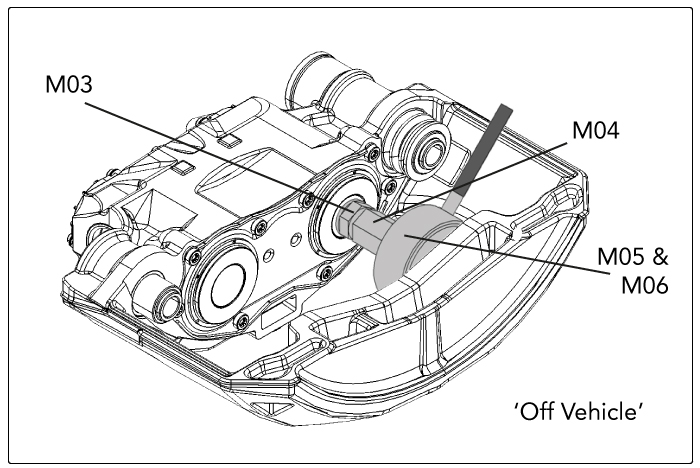
12. Release the tool and turn tool M06 over, within M05, so that the open side of M06 makes contact with the tappet boot seal. Ensure it is centralised on the tappet.

13. If the caliper is removed from the vehicle then add tool M04 (between M03 & M05). Press the tappet boot seal into place by winding out M03 against the brake disc, or the outboard pad abutment face if the caliper is removed from the vehicle, until it stops. Repeat the process for both tappets.

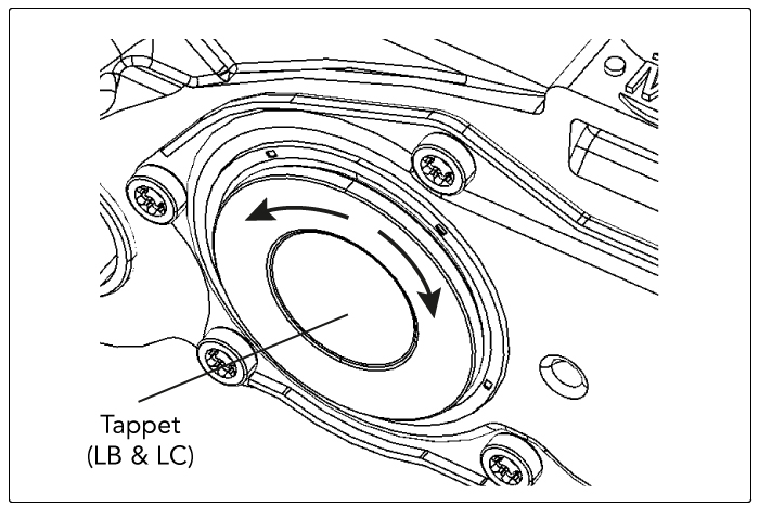
14. After assembly check that the tappet boot seal assemblies are securely attached by pulling them lightly by hand. Check that the tappets are free to rotate slightly in each direction, taking care not to over-stress the tappet boots.
Note: LV225 & LA225 tappets (ref. MEI kit 5R0405) are identified by an annular groove on the outer face.
 |
 |
15. If the caliper has been removed from the vehicle then replace as detailed in the GUIDE SLEEVE SEAL AND BUSH REPLACEMENT section. Refit the brake pads as described in the PAD REPLACEMENT section (this can be found on p.7-8 of the MEI Caliper Maintenance Guide).
Note: If the brake is removed from the vehicle then new axle mounting bolts should be used for re-installation.
Pad Replacement
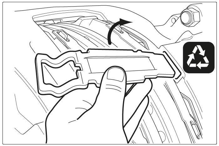
Remove the wheel (referring to the vehicle manufacturer’s recommendations). Remove the pad retainer by removing the spring clip and washer then depressing the pad retainer to remove the pin. If necessary remove any pad wear warning indicator (PWWI) cable & clips (note the cable arrangement for fitting a new PWWI).
! Depending on the orientation of the caliper the brake pads could fall out when removing the pad retainer.
 |
 |
 |
Remove the adjuster cap. Fully wind back the tappets, using a 10mm ring spanner or socket wrench, by turning the adjuster anti-clockwise as viewed from air chamber side.
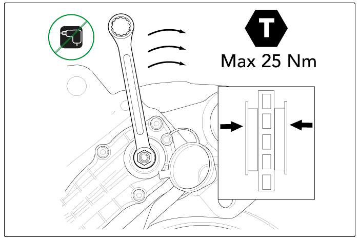
! Never exceed a maximum torque of 25 Nm in either direction, and never use power tools.
Note: when turning anti-clockwise a noticeable clicking can be heard & felt.
 |
 |
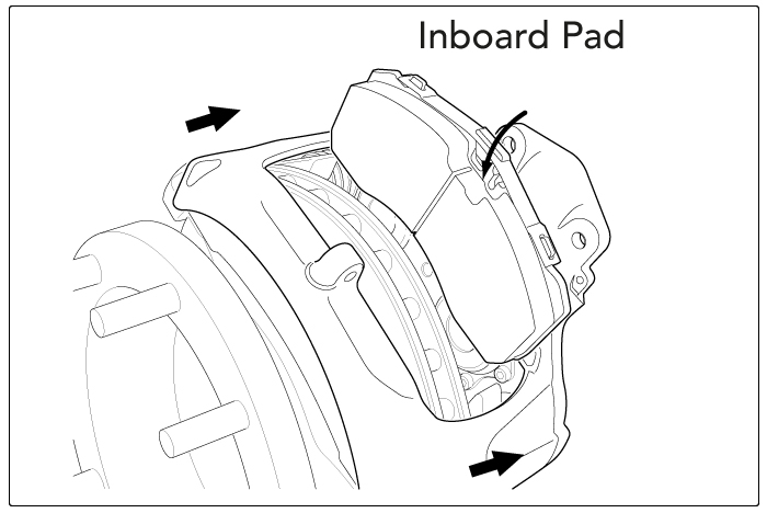
Remove the worn brake pads and then check the caliper sliding. Note that the geometry of the LC225 brake requires that the caliper is pulled towards the outboard side first in order to remove the outboard pad and then pushed towards the inboard side to remove the inboard pad.
Check the rubber boots and replace if necessary. Clean the pad abutments of the carrier if required, taking care not to damage the rubber boots. Check the brake disc thickness and for signs of heavy grooving, cracking or corrosion.
Fully wind back the tappets using a 10mm ring spanner or socket wrench by turning the adjuster anti-clockwise as viewed from air chamber side and fit the new brake pads. Note that the geometry of the LC225 brake requires that the caliper is pushed towards the inboard side to fit the inboard pad first and then pulled towards the outboard side to fit the outboard pad.
 |
 |
! You must always replace the brake pads on both brakes across an axle.
! Ensure old brake pads are disposed of in accordance with local environmental regulations.
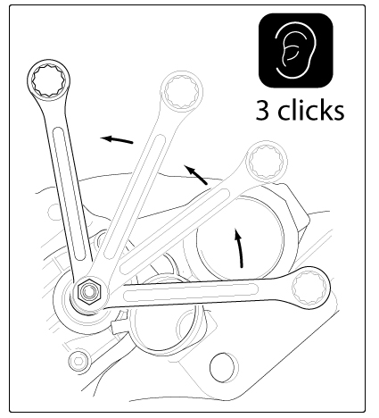
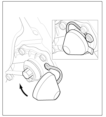
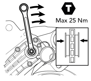
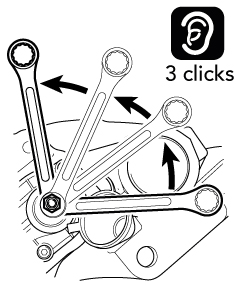
Turn the adjuster clockwise until the pads come into contact with the disc – do not exceed 25 Nm torque. Turn back the adjuster anti-clockwise 3 clicks and check the pad-to-disc running clearance – there should be free rotation of the disc. Refit the adjuster cap.
 |
 |
 |
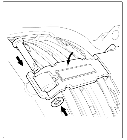
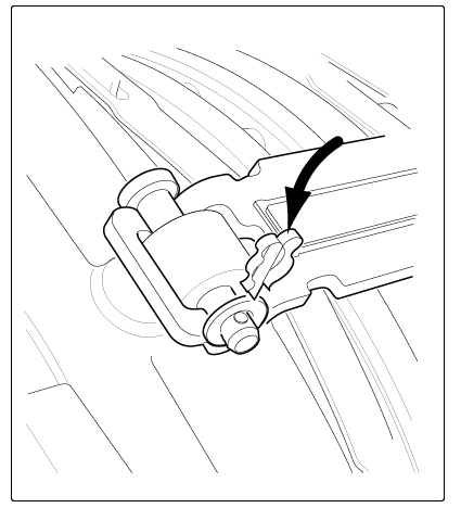
Locate the new pad retainer in the slot in the caliper and depress to enable the insertion of the pad retainer pin. Locate the washer over the pad retainer pin, then press the clip through the pad retainer pin to secure.
 |
 |
 |
Note: it is recommended that pad retainer pin, where possible, is installed with pin head uppermost.
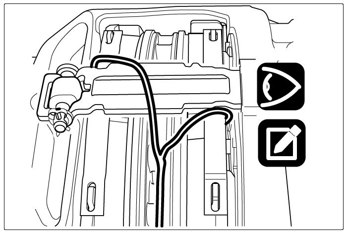
If applicable, fit a new pad wear warning indicator (PWWI) cable & clips in the same orientation as they were removed.
 |
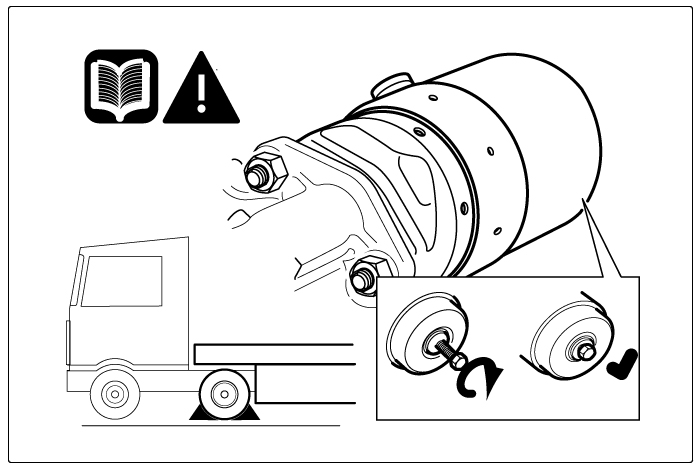 |
Replace the wheel in line with the vehicle manufacturer’s recommendations. Uncage the spring brake and apply the parking brake prior to removing the chocks from the vehicle. After releasing the parking brake, apply the brake 10 times then road test the vehicle to bed the pads and check the brake performance.
! Remember that there may be a lower performance during the bedding-in phase of the new brake pads.
Chain Cover Replacement
1. Replacement of the chain cover assembly should only be undertaken to replace a damaged chain cover or wear sensor – if there are any signs of water ingress then the complete caliper should be replaced.
 |
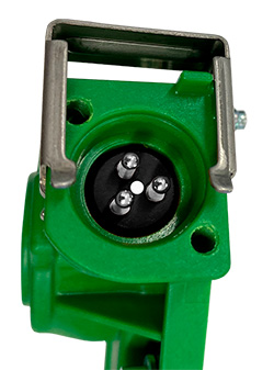
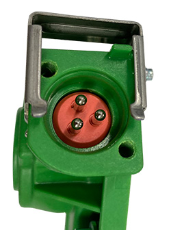
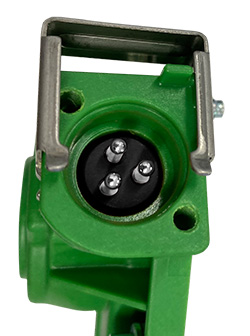
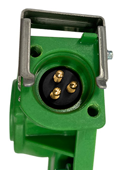
Identify the type of sensor by the electrical connectors – only replace with the same type. MEI ‘universal’ chain covers are also available to accommodate either screw type or clip type connectors. |
 |
 |
 |
 |
 |
 |
|
On/Off - Silver Pins + White Circle |
New On/Off - Red Block |
Linear - Silver Pins |
Stepped - Gold Pins |
Screw Type | Clip Type |
Clean any dirt from around the plastic chain cover to be replaced and remove the electrical connector, being careful that nothing falls into the air chamber pushrod aperture.
MEI chain covers with sensors are supplied pre-set in the correct position however the caliper pistons need to be set to match this – it is recommended that this is done with the brake removed from the vehicle.
2. Adjust the tappets using a 10mm ring spanner or socket wrench on the adjuster until a setting gap ‘P’ (see table) is achieved between right hand piston and outboard pad abutment face – do not exceed 25 Nm torque.
 |
... |
Caliper Variant + Chain Cover Variant |
Setting Gap (P) |
Voltage (Ref. Only) |
||
| LB195, LB225 or LC225 + Plain Type Chain Cover |
105 ± 0.25 mm | n/a | ||||
| LB195 or LB225 + Silver Pins + White Circle |
105 ± 0.25 mm | 0.15 V | ||||
| LB195 or LB225 + Silver Pins |
105 ± 0.25 mm | 1.0 V | ||||
| LB195 or LB225 + Gold Pins |
105 ± 0.25 mm | 0.7 V | ||||
| LA225 or LV225 + Silver Pins + White Circle |
110 ± 0.25 mm | 0.15 V | ||||
| LA225 or LV225 + Silver Pins |
110 ± 0.25 mm | 1.0 V |
MEI chain covers with sensors are supplied pre-set at the correct voltage, but if required the voltage can be checked using the MEI Wear Sensor Tester (ref. 5K2010).
With the chain cover mounting face uppermost remove the chain cover assembly to be replaced by loosening the 7 screws using a 4mm A/F hexagon drive and lift the cover away from the chain.
 |
|
|
Do not disturb the synchronisation of the chain and sprockets. |
3. With the chain cover mounting face uppermost, clean the sealing interface on the caliper housing by wiping radially away from the chain with a clean cloth, being careful not to get any dirt into the screw holes. If necessary re-align the chain to match the profiled channel in the underside of the plastic chain cover.
 |
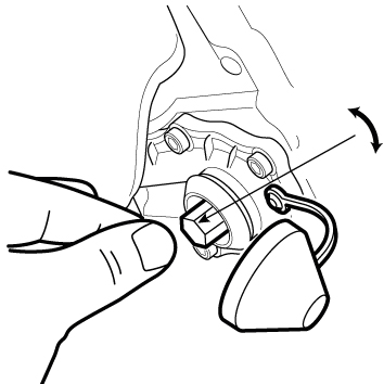 |
Locate the small plastic wear sensor drive adaptor (where applicable) in the end of the secondary adjuster shaft.
Position the new chain cover assembly, with the adjuster cap removed, over the chain and sprockets and lower it into place to align the wear sensor with the drive adaptor (where applicable) and the 7 screws with the threaded holes. Gently rotate the adjuster drive by hand, by no more than 15 degrees in either direction, to ensure it locates over the adjuster shaft and the chain, and the chain cover gasket comes into full contact with the caliper housing.
Loosely wind down the 7 screws using a 4mm A/F hexagon drive. Tighten the screws to 5 - 6 Nm torque in the numbered sequence (1-7) shown.

4. Refit the brake to the vehicle. Replace the pads and re-set the running clearance by turning the adjuster clockwise until the pads come into contact with the disc – do not exceed 25 Nm torque – then turn back the adjuster 3 clicks and check the pad-to-disc running clearance.
 |
... |  |
5. Replace the adjuster cap.

Refit the electrical connector to the chain cover.
 |
... |  |
... |  |
| Screw Type | Clip Type |